Microfluidic Devices
This experiment was developed by Jennifer Gilbertson, Melissa Hemling and George Lisensky, based on the work by A. Grimes, D. N. Breslauer, M. Long, J. Pegan, L. P. Leeb and M. Khine, "Shrinky-Dink microfluidics: rapid generation of deep and rounded patterns", Lab on a Chip, 8, 170-172 (2008).
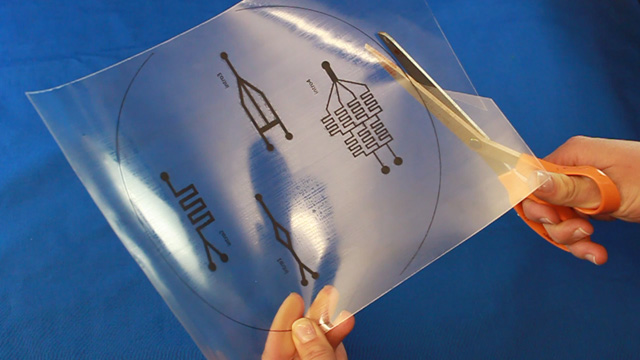
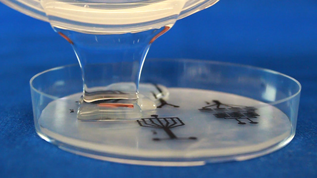
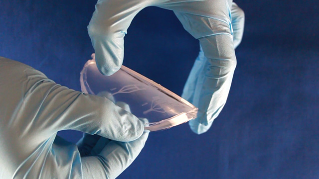
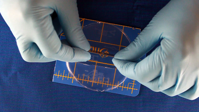
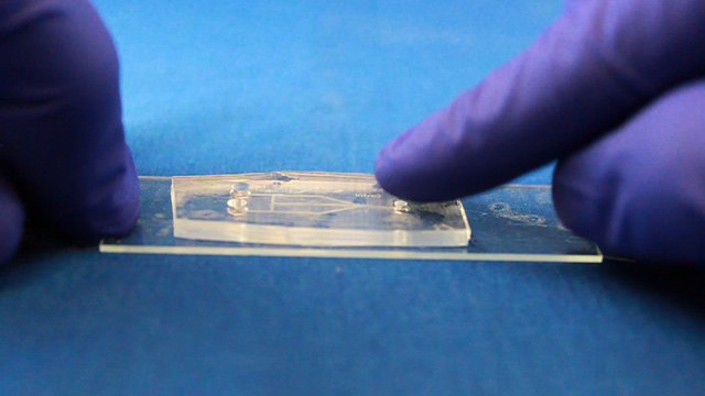
Biaxially oriented polystyrene thermoplastic sheets (Shrinky Dinks) will contract to about 50-percent of their original size when heated, becoming thicker and hard. Any printing on the sheets will become a raised pattern which can used as a mold. In this experiment the printing will be lines drawn where fluid should flow. Polydimethylsiloxane (PDMS) can be cured by an organometallic crosslinking reaction to give an optically transparent polymer with the ability to reproduce surface features. In this experiment the PDMS is cured in contact with the Shrinky Dink mold to create channels that correspond to the original printing. Peeling the PDMS from the mold and attaching it to a glass slide produces a microfluidic device.

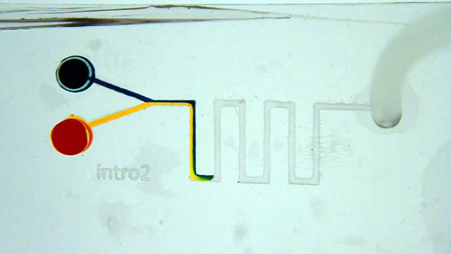
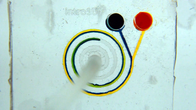
In addition to important applications where very small quantities of reagents are used, the small dimensions of the microfluidic channels alter the behavior of fluids compared to the macroscale. Microfluidic devices exhibit laminar flow where parallel fluid streams in the same channel will flow independently of each other with little or no mixing at the interface.
| Procedure | Wear eye protection |
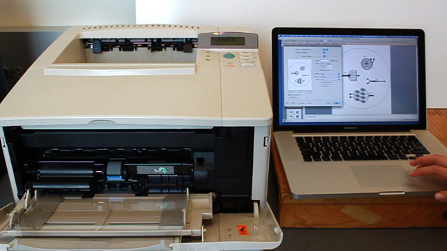
Using Powerpoint, create a drawing of a microfluidic device. The size of indvidual patterns should be no bigger than 2" by 3" to allow the shrunken design to fit on a standard microscope slide. Several devices can be drawn within an 8.4 inch circle. Leave space between them so the PDMS casts can be cut out individually and stay at least 1/2 inch from the edge of the circle. Line widths of 2 or 3 points work well but may vary with individual laser printers (see the test patterns). There should only be one outlet. Use the sample file as a guide.
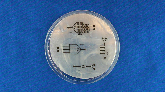
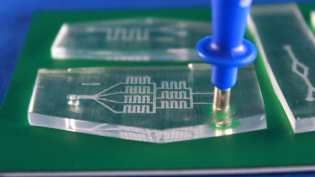
Syringe option: two 3 mm inlets and one 2 mm outlet.
Pump option: two 1.5 mm inlets and one 3 mm outlet.
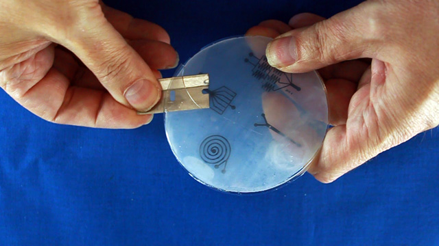
Always use the punch on a cutting mat. Do not press on the plunger while cutting. (Press the plunger afterward to eject the core.)
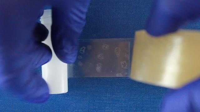
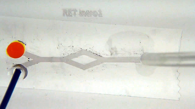
Attach hose connectors to both 1.5 mm inlet holes. Connect the pump tubing to the inlet hose connectors. Use the pump to slowly push differently colored solutions through the two channels. Do the streams of food coloring exhibit laminar flow as the solutions are pushed through the channels? Do your observations vary with flow rate?
Both Options
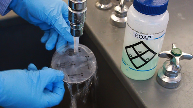
If your device does not work, try assembling the same device again. You might clean your device for re-use by running water through the device or disassembling the device and rinsing with water. Use tape (by pressing and peeling) to remove macro dirt or dust particles from the PDMS mold prior to assembling the device. Watch carefully as your press the device to the tape: you want all the flat parts and only the flat parts to connect to the tape.
Conclusions
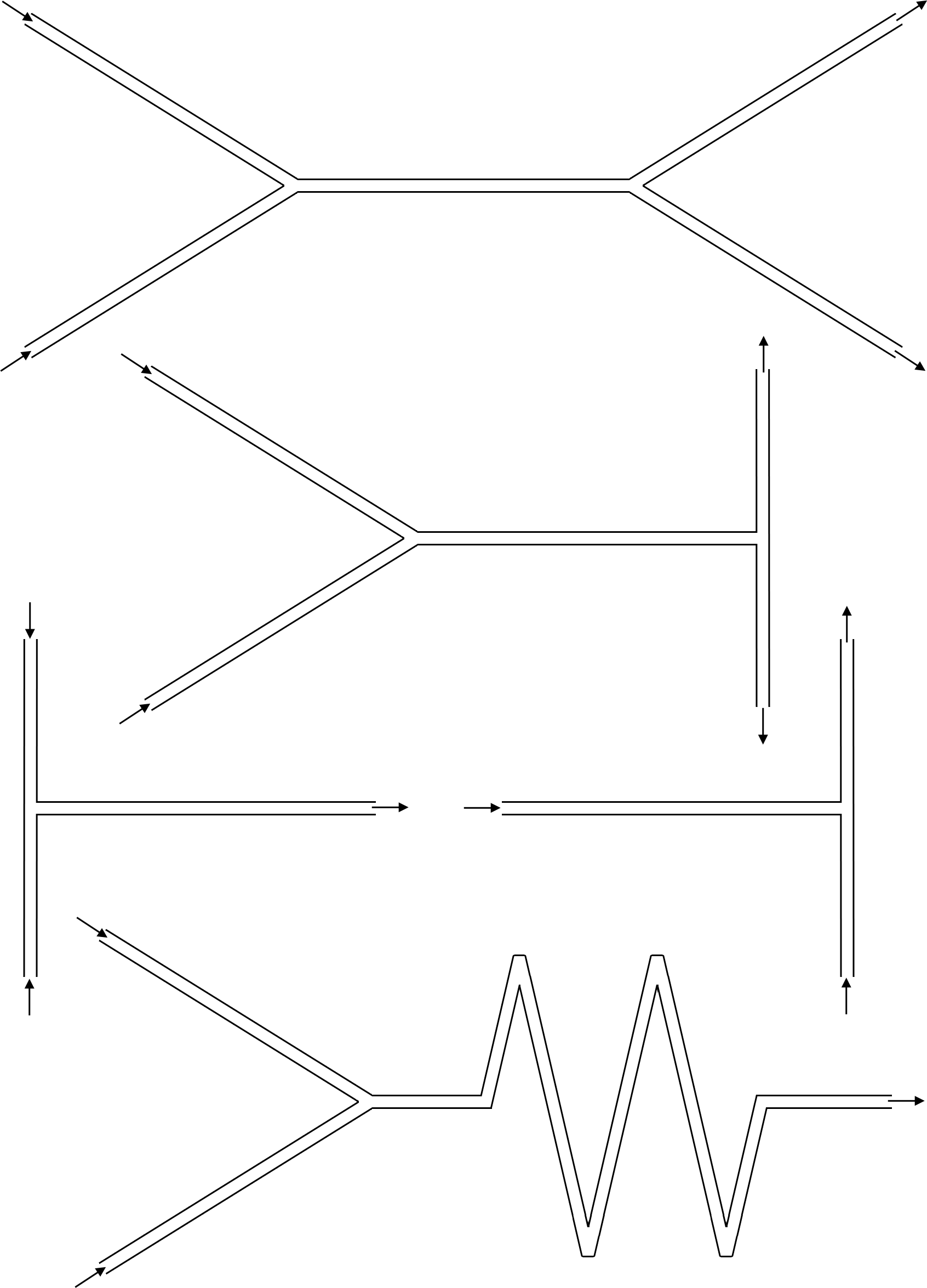
- Report your observations by taking a photograph or video or using colored pencils to make a sketch of your results while the liquid is slowly flowing for each tested pattern.
- What happens at a Y-junction? What happens at a T-junction? What happens at square corners (90° turn)? What happens at zig-zag corners (<90° turn)? Sketch your answers on the figures below.
- Do your observations vary with flow rate? Be sure to test very slow flow. How could you measure flow rate?
- What features of a microfluidic device promote turbulent flow (mixing)? What features of a microfluidic device promote laminar flow? How do you know?
- Compare your results with those from another group that used the other option. Does pushing or pulling work better?
- Clear Shrinky Dinks Film (Grafix KSF50-C 8-1/2-Inch by 11-Inch Shrink Film, Clear, 50-Pack)
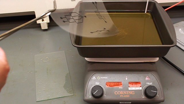
- Corn oil (may be reused)
- Soap and sink for washing off corn oil
- Aluminum foil for protecting surfaces
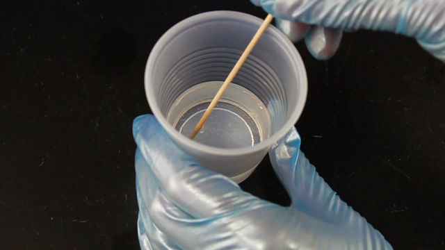
- PDMS base and curing agent (Dow Corning Sylgard Elastomer 184 Kit, available from Ellsworth Adhesive)
- Plastic cup or large weigh boat for mixing PDMS
- Wood stir sticks or popsicle sticks for stirring PDMS
- Double Sided Tape (Scotch 665 Double-Sided 1" Tape is available from Nordisco, MMM 66511296. Smaller devices can use standard 1/2" double sticky tape.)
- Petri dishes (100 mm, vented, non-sterile, VWR 25384-045)
- Disposable plastic pipettes (extended fine tip, non-sterile, VWR 16001-192)
- Food coloring. Use neat or dilute a little. You want to be able to see the color of a very thin sample.
Equipment
 Core punches
- Powerpoint for drawing patterns (sample file)
- Laser printer
- Scissors
- 9x9" brownie pan for the corn oil
- Hot plate
- Thermometer
- Tongs
- Glass plates
- 0.01g balance or volume measuring dispensers for PDMS
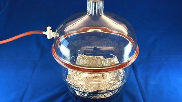
- Vacuum Desicator with pump
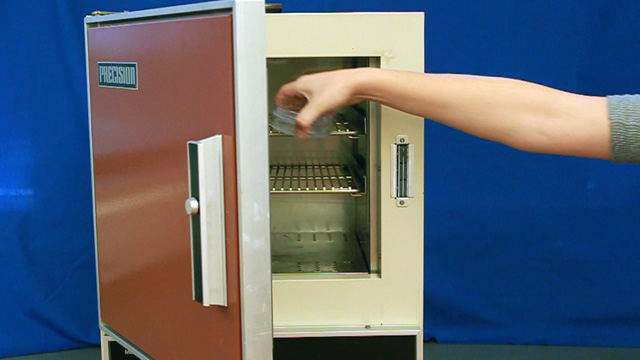
- Oven for curing PDMS (70°C)
- Single-edge razor blades for cutting PDMS
- Punches and cutting mat (Harris Unicore 2mm and 3mm).
- A less expensive punch alternative can be fabricated from 1/8 x 0.014 inch round brass tube. A tubing cutter is used to cut the tubing into 3 inch lengths and a grinding wheel is used to sharpen one end. If the core gets stuck in the punch use a copper wire to eject the PDMS core.
- Cutting mats are also available at fabric stores.
- Glass microscope slides (standard 25 x 75 mm)
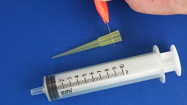
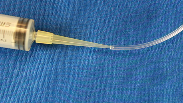
- 10 mL plastic syringe fitted with micropipet tip
- 2 mm tubing (.030"ID x .090"OD Tygon Tubing)
University of Wisconsin Materials Research Science and Engineering Center
Interdisciplinary Education Group | MRSEC on Nanostructured Interfaces
This page created by George Lisensky, Beloit College. Last modified September 11, 2018 .