Polyhedral Model Kit
What You Need to Know
Anions are generally larger than cations. Many solids can be viewed as a close-packed array of anions with the spaces between the anions occupied by cations. Those spaces have tetrahedral and octahedral geometry - the same geometries as the structural units in this model kit.
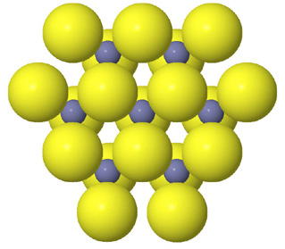 Tetrahedral spaces between two anion layers in the zinc blende, ZnS, structure. |
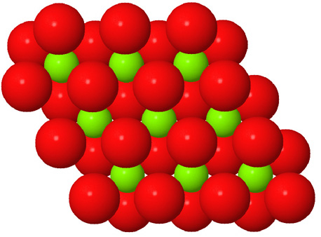 Octahedral spaces between two anion layers in the brucite, Mg3(OH)6, structure. |
|
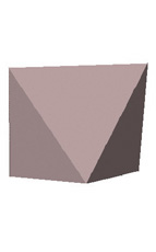
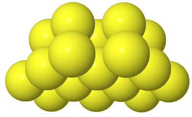  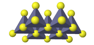 Side view of two anion layers in the zinc blende, ZnS, structure. Which representation best helps you to visualize the structure? |
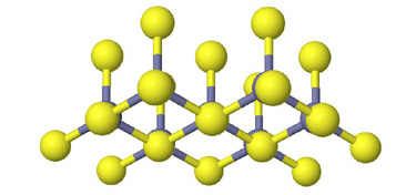
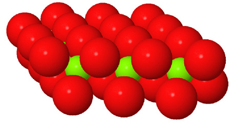 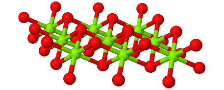 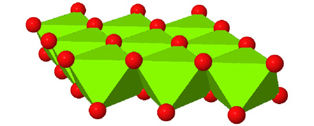 Side view of two anion layers in the brucite, Mg3(OH)6, structure. Which representation best helps you to visualize the structure? |
Since in some respects all of these representations are valid, the important
question is not really which representation is correct. What is important is
what you can learn from each and that using multiple representations will enhance
your visualization of the structure.
Models are designed to represent some features of the world. Models that show
arrangements of atoms have their limitations, since atoms are not spheres and
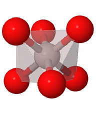
bonds are not sticks. Polyhedral models are designed to show how atoms arranged
in structural units such as tetrahedra and octahedra fit together.
Because they consist of structural units instead of individual atoms, polyhedral
models can be assembled quickly. By focusing on units larger than atoms, patterns in complex structures can be more easily discerned.
Since models are simplifications they also introduce errors. This is not a problem
if you remember that models are just models and you realize the following.
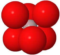
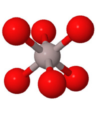
- In most cases the cations in this model kit are located at the center of the polyhedron and the anions are located at the corners of the polyhedron. The edges of the polyhedra do not represent bonds but do serve to define the polyhedral shape. Because the connectors that hold adjacent polyhedra together are at the corners, they can be thought of as representing atoms or ions.
- Anions are generally larger than cations. (See the discussion at the beginning of this section.) This means that the atom represented by the colored pompom at the center of the polyhedron is actually smaller than the atoms represented by the corners of the polyhedron. The space-filling view (above left) more correctly indicates relative ion sizes.
- The tetrahedra and octahedra in this model kit are highly symmetric. In real crystals all six anions surrounding a cation may not be at the same distance and not all the bond angles may be the 90° expected for an octahedron. Four anions surrounding a cation may not be a perfect tetrahedron or even square planar. The models you build will however be close enough to help you visualize the atomic relationships that are more accurately shown in the illustrations. The computer-generated illustrations in this manual and in its online companion are based on actual atomic positions determined by x-ray crystallography.
- The tetrahedra and octahedra in this model kit come in only one size. Real crystals can be constructed from many different elements with different degrees of ionic and covalent bonding, resulting in variations in atomic size. The computer-generated illustrations in this manual and in its online companion are based on average ionic radii for the observed coordination number and oxidation state as assigned by Shannon and Prewitt based on x-ray crystallographic data (Acta Cryst., A32, 751 (1976) and J. Amer. Chem. Soc., 111, 5707 (1989)). In our illustrations we have, however, used an ionic radius for H+ of 0.5 Å (0.05 nm or 50 pm). This too-large value was chosen so that hydrogen could still be observed in the space-filling view. Again the models you build are to help you visualize the atomic relationships that are more accurately shown in the illustrations.
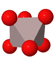
Close packed arrays of oxide ions
are the basis of many mineral structures and are important for understanding
geochemistry. Geochemists routinely use the representation at the far right.
This page created by George Lisensky, Beloit College. Last modified April 25, 2015 .