Preparation of an Organic Light Emitting Diode
Modification by Jason Marmon, George Lisensky, and Wendy deProphetis from Frank G. Gao and Allen J. Bard, "Solid-State Organic Light-Emitting Diodes Based on Tris(2,2'-bipyridine)ruthenium(II) Complexes," Journal of the American Chemical Society, 122(30), 7426-7427 (2000) and Hannah Sevian, Sean Muller, Hartmut Rudmann, and Michael F. Rubner, "Using Organic Light-Emitting Electrochemical Thin-Film Devices to Teach Materials Science," Journal of Chemical Education, 81(11), 1620 (2004).
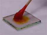
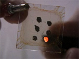
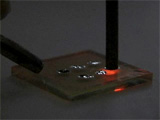
A coordination complex between a transparent tin oxide electrode and an active metal electrode produces light when an external voltage is supplied. Too thin a coating of the [Ru(bpy)3](BF4)2 polyvinylalcohol layer will give a short circuit and no light; too thick a coating will have a large electrical resistance and no light.
| Procedure | Wear eye protection |
Chemical gloves recommended |
Is the circuit a diode? What happens if you reverse the polarity of the applied voltage?
Conclusions
- How many layers of the [Ru(bpy)3](BF4)2 polyvinylalcohol solution did you apply? What would you recommend? Does a thin coating or a thick coating work better?
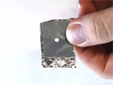
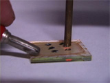
- How many gallium-indium dots did you apply? How many of them could be made to give off light? Are there any differences between those that light and those that do not light?
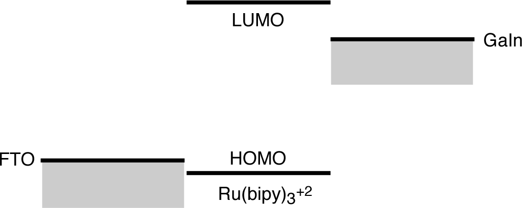
- How does the circuit produce light? Use an energy level diagram to illustrate your answer and include the battery.
- Is the circuit a diode? How do you know? How do you distinguish your observations from what you would observe if the OLED stopped working?
- Stock Solutions for multiple preparations.
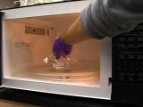
- Place approximately 0.30 g PVA (polyvinyl alcohol, Aldrich, 36,316-2, Average MW 124,000-186,000) and 10 mL of water in a 30-mL beaker. Cover the beaker with a watch glass or loosely with plastic wrap. Dissolve the PVA by heating the mixture in a microwave for 5-15 second increments. Do not allow the solution to boil. Stirring with a glass rod may help.
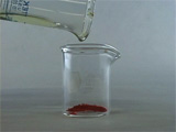
- Dissolve approximately 0.035 g [Ru(bpy)3](BF4)2 (Synthesis) in 3 mL of polyvinylalcohol solution. If a solution dries out, add more water and redissolve.
- GaIn Eutectic, Aldrich, 49542-5
- Equipment
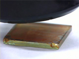
- Conductive Glass (1" x 1" x 2.3mm TEC 15 glass), Hartford Glass Co, 735 E Water Street, Hartford City, IN 47348 Phone: 765-348-1282
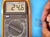
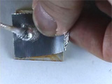
- Ohmeter
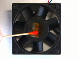
- 2500 rpm fan and power supply, Radio Shack 273-243B 12VDC Cooling Fan, 273-1662 Universal Power Adapter
- Double-stick tape
- Template masks made from aluminum foil, duct tape, 2/16" hole punch
- Cotton swabs
- Hair dryer
- 4.5-Volt power supply
University of Wisconsin Materials Research Science and Engineering Center
Interdisciplinary Education Group | MRSEC on Nanostructured Interfaces
This page created by George Lisensky, Beloit College. Last modified May 13, 2019 .