This procedure was developed by Fabian Dauzvardis, Tess Jacquez and George Lisensky from
Projekt Brændselscellen by Gunnar Cederberg & Kim Rongsted Kristiansen.
Fuel cells are devices that convert a fuel (hydrogen) and an oxidant (oxygen) directly into electricity without combustion.
The fuel is oxidized at one electrode and the oxidant is reduced at the other electrode. In an alkaline fuel cell the half reactions are
By running the reaction in two cells the electrons being transfered in the overall redox reaction will go through a wire to complete the circuit.
A catalyst, such as palladium, can be used to increase the rate of reaction.
A fuel cell will continue to generate electricity as long as it is supplied with fuel and oxidant.
An alkaline fuel cell was used by NASA in the Apollo moon landings and in the Space Shuttle.
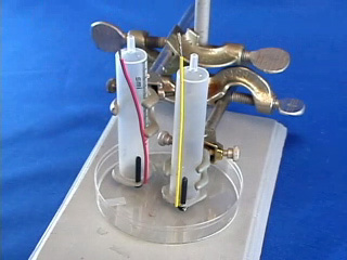
Clamp two syringes with mesh in a Petri dish or use an alternative syringe holder. The palladium coated nickel mesh should be close to the bottom of the dish, so let the plastic screw head touch the bottom.
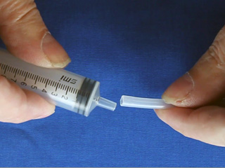
Obtain two pieces of polythelylene tubing. Prestretch ONE end of each by forcing it over the tip of a spare syringe.
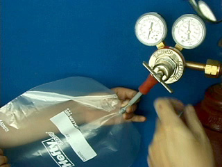
Obtain two slider storage bags with an attached thin stem dropper. Insert the dropper into a hose connected to a hydrogen tank. Fill the bag with hydrogen. Slip the unstretched end of the tubing over the dropper tip. Similarly prepare another bag with air (not shown) using the compressed air supply in the fume hoods.
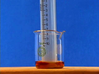
Connect the prestretched end of the tubing from the gas-filled bag to the syringe assembly. Apply pressure to the hydrogen bag to flush out the syringe. (This is important! If the syringe is not full of hydrogen the fuel cell will not work.) Connect the voltmeter to the wires. Lastly add 1.0 M NaOH solution to the Petri dish so as to just reach the wire mesh. (This is also important! The mesh needs to contact both the solution from below and the gas from above.)
Place something on the bags to maintain pressure and keep the liquid level in the syringes matched with the mesh level.
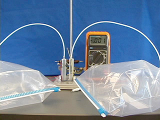
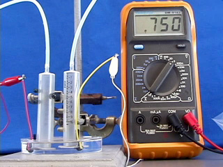
Turn the voltmeter from "off" to the V setting to measure voltage. For the first few minutes the voltage might increase. Adjusting the pressure may help.
Record the voltage then turn the meter to the mA setting and measure the current in milliamps.
Testing the fuel cell
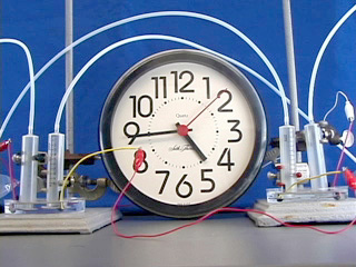
Combine your cell with another group to produce a maximum voltage. Which electrode should be connected to which electrode? What is the measured voltage? What is the measured current? Replace the meter with a 1.5 V clock that provides a convenient way to measure how long the fuel cell works.
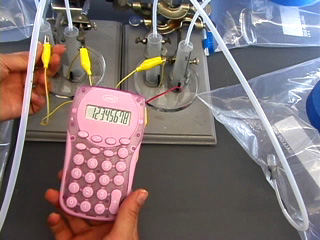
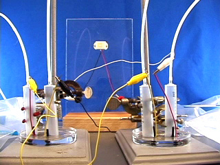
Two connected fuel cells may operate a calculator (left) or a piezoelectric buzzer (right). Combine your cell with another group and try some hydrogen powered math. Which electrode should be connected to which electrode?
Be sure you have collected all of the data you need to answer the questions.
When finished please rinse the mesh on the end of the syringe with water before returning the equipment.
Questions
Did your fuel cell work? Include the current and voltage (with units) produced by your fuel cell in your conclusions. How much power is produced? (energy/time = volts x amps = watts)
Connect together more than one fuel cell. How did you assemble them together to produce a maximum voltage? A sketch will help. How much power is produced?
What is the function of each part of the fuel cell you built? One way to answer this question is to follow the path of an electron through the complete circuit.
What were you able to power using your combined fuel cells? How long did they work?
Compare results for fuel cells with and without the palladium coating. Include both the current and voltage (with units). What is changed by adding the palladium catalyst?
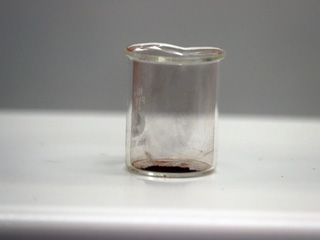
20 mL beaker for deposition step (syringe and mesh just fits inside)
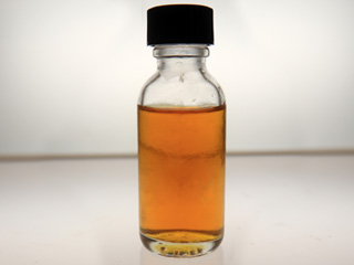
Dissolve 0.05 g PdCl2 with heating in 0.5 mL conc HCl in a 10 ml beaker in a fume hood.
Dilute to 25 mL with water to give a 0.010 M PdCl2 solution.
Use this solution for coating the nickel mesh:
Pd+2(aq) + Ni(s) → Pd(s) + Ni+2(aq).
1.5 mL of this solution can be used for about 20 minutes of electroless deposition (until color is mostly gone.) If the cell stops working, repeat the PdCl2 deposition.
Cell Pre-Assembly
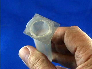
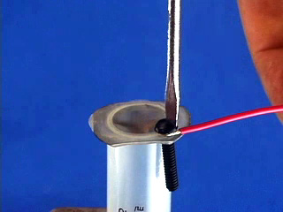
Heat a hotplate to approximately 170°C (Corning digital hotplate setting of 220; we use an oven thermometer to check the surface temperature). Put a nickel mesh on a glass slide in the center of the hotplate. The glass slide protects the hotplate. Do only one sample at a time. Set a 10 mL plastic syringe body (with plunger removed) onto the nickel mesh. After the plastic starts to melt, press down gently. Remove the syringe, mesh, and attached glass slide from the hotplate.
The syringe and the nickel mesh will stick to the glass slide until they cool. The end of the syringe should be attached to the mesh all the way around and the center of the mesh should not be coated in plastic. If the syringe is only partially sealed to the nickel mesh, heat again.
Repeat to assemble a second syringe and mesh.
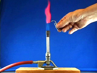
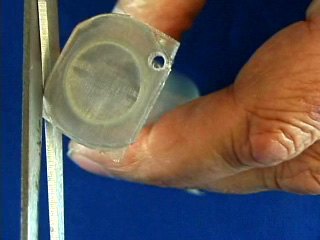
Use a hot pointed paper clip to melt a pilot hole through the net and syringe base. Widen the pilot hole using a drill (7/64" or #36 bit).
Twist in a 6-32 tap to thread the drilled hole.
Use scissors to trim any excess nickel mesh that extends beyond the syringe bases. (Trimming off excess nickel mesh uses palladium more efficiently in the next step.)
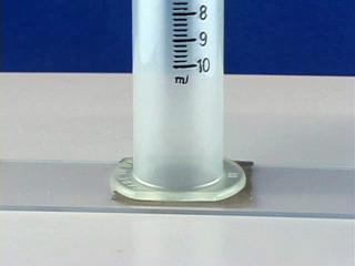
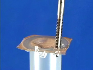
Place 1.5 mL of PdCl2 solution in a 20 mL beaker.
Use a working syringe to pull the solution through the mesh of one syringe assembly. Remove after 4 minutes. Plate the second syringe in the same solution for 4 minutes.
(The palladium solution is good for a total of about 20 minutes of coating.) After plating rinse the mesh with water.
Screw a 6-32 bolt part way into the hole. Strip both ends of a 4" piece of wire. Bend one end around the bolt and screw the bolt in the rest of the way. Do this to both syringe assemblies.
Gas Bag Pre-Assembly
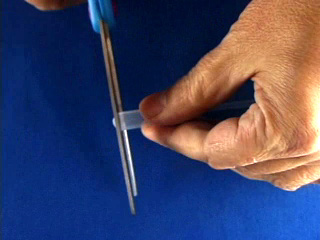
Cut off a very small portion of the end of the bulb of a 1.5 mL thin stem plastic dropper. Make two of these.
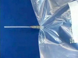
Poke a small hole (smaller than the diameter of the dispensing end of your plastic dropper) in the center of the bottom edge of a one gallon slider storage bag. Insert the tip of a modified dropper through the hole.
Wrap duct tape around the bag and dropper to seal the joint. Make two of these. Close the bag slider.